2013年12月25日星期三

Image the outer layers.

Hello,we are HQEW PCB...We image the outer layers in a clean room to make sure that no dust gets onto the panel surface where it could cause a short or open circuit on the finished PCB.
The panel is first coated with a layer of photosensitive film, the photoresist, which is hot-rolled onto the copper using a cut-sheet laminator. The laminated panels are collected by an automatic rack. The clean room uses yellow lighting as the photoresist is sensitive to UV light.


The bed of the printer has registration pins matching the holes in the phototools and the panel. The operator loads the first film onto the pins, then the laminated panel and finally the second film. The pins ensure that the top and bottom layers are precisely aligned. The printer uses powerful UV lamps to harden the photoresist. So the photomask is clear where we want the resist to harden and black where we don’t want resist.
The Mylar film which protected the photoresist is now removed and the imaged panel is conveyored out of the clean room and through a developer which removes the unhardened resist. For inner layers the copper pattern we want was covered by the resist. For outer layers it is exposed ready to be plated. The operator now checks the panels to make sure that the copper surface is clean and all the unwanted resist has been removed.

2013年12月18日星期三

Electroless copper deposition

The first step in the plating process is the chemical deposition of a very thin layer of copper on the hole walls.  The operator clamps the production panels into the jigs.  The line is fully computer controlled and the panels are carried through a series of chemical and rinsing baths by the overhead crane.  Almost all PCBs with 2 or more copper layers use plated through holes to connect the conductors between the layers.  A good connection needs about 25 microns of copper on the walls of the holes.  This thickness must be electroplated, but the walls of the holes are non-conductive glass cloth and resin.  So the first step is to deposit a conductive layer over the hole walls.  We use electroless copper, that is we deposit chemically a layer of copper about 1 micron thick over the walls of the hole (and incidentally across the whole panel).  This is a multi-stage process as you see from the video with washing steps between the stages.  We pre-treat the panel, then we seed the hole wall with micro-particles of palladium, and finally deposit the copper

Alice skype: hqew-four

2013年12月6日星期五

Drilling the PCB

Drilling printed circuit boards

X-ray drill of reference holes

Now we drill the holes for leaded components and the via holes that link the copper layers together.  First we use an X-ray drill to locate  targets in the copper of the inner layers.  The machine drills registration holes to ensure that we will drill precisely through the centre of the inner layer pads.

Prepare the stacks for drillng

To set up the drill the operator first puts a panel of exit material on the drill bed.  This stops the drill tearing the copper foil as it comes through the PCB.  Then he loads one or more PCB panels, and a sheet of aluminium entry foil.

Drilling the holes

The drilling machine is computer-controlled. The operator selects the right drill program.  This tells the machine which drill to use and the X Y co-ordinates of the holes.  Our drills use air-driven spindles which can rotate up to 150,000 revolutions per minute.  High speed drilling ensures clean hole walls to provide a secure base for good plating on the hole walls.
Drilling is a slow process as each hole must be drilled individually.  So depending on the drill size we drill a stack of one to three PCB panels together.  We can drill holes down to 100 microns in diameter.  To give you an idea of the size, the diameter of a human hair is about 150 microns.  Drill change is fully automatic.  The machine selects the drill to use from the drill rack, checks that it is the correct size, and then loads it into the drill head.
Once all the holes are drilled the operator unloads the panels from the drilling machine and discards the entry and exit material.
http://www.aliexpress.com/store/432347


Cut-off excess resin

During bonding excess resin from the prepreg is squeezed to the edge of the panel outside the image area.  This excess is now cut off on a computer controlled profiling machine.  The operator loads the panel onto the bed of the machine and selects the correct program with the X y co-ordinates of the path for the cutter to follow.  The drilling machine uses the points of the drill but the profiling machine uses the specially patterned shank of the tool. The cutter mills out the final profile for the production panel.  The drilled panel is now ready for plating.

2013年12月2日星期一

PCB manufacture step by step:Double-sided PCB

First ,make the gerber file to be PCB production data.

The board designer has prepared his layout on a Computer Aided Design or CAD system.  Each CAD system uses its own internal data format, so the PCB industry has developed a standard output format to transfer the layout data to the manufacturer.  This is Extended Gerber or RS274X.  The Gerber files define the copper tracking layers (4 in the job we are following) as well as the soldermasks and component notations.
First we check that data meets our manufacturing requirements.  These checks are mostly done automatically.  We check the track widths, the space between tracks, the pads around the holes, the smallest hole size etc.  The engineer can also check and measure individual areas where he wishes.  Once the data is verified as good he will output all the tool files needed to drive the machines that will make and test the PCB.


PCB manufacture in China :Alice 
skype: hqew-four

The scrolling LED strip(2)


As you can see from that video, column are lit in a batch, but one row at a time. When done really slowly you can't make out the whole letter. When sped up, persistence of vision makes it appear that they are all on at once.

Detail from the reverse side:


Keypad driver


One slightly puzzling aspect was the absence of any extra chips for the 55-key keypad, as all 10 chips had now been accounted for. There were 8 wires leading to it (on a ribbon cable) on the left, in the photo, and 7 wires on the right. This led to a deduction that this was a 7 x 8 key keypad matrix. Since that would give 56 possible keys, it seemed very likely.

A close inspection of the cable on the left showed 8 x 10k pull-up resistors for that cable, plus each of the 8 wires were connected directly to the CPU. On the other side, the "row driver" chip was also connected to the 7-wire cable going to the keypad.

Thus it seems that the design was that the row driver would be repeatedly activated for one row at a time (driving it low) which would source current for the LEDs via the transistors which invert the signal, plus at the same time sink current for the keypad (the keypad does not go via the transistors). The pull-up resistors would raise the input to the CPU high, except if a key was pressed. Thus the CPU could deduce which key was being pressed, while it was also outputting to the LEDs.


Taking control!


Knowing how the 595 works, it seemed reasonable to assume that if I could disconnect the clock, data, and latch signals from the processor, and supply my own, then I could make the LEDs show whatever I wanted.

After a considerable amount of time tracing PCB traces, I worked out that it was very easy to do, because each of those reached the processor chip via a jumper on the front.

To do this cut the three jumpers indicated and then solder wires onto the circled ends of the now-cut link (that is the part furthest from the processor).


Now the processor thinks it is sending data to the 595 chips, but it isn't.

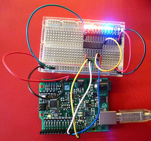
Those three wires (clock, data, latch) are then connected to the Arduino as shown (pin numbers for a Uno or similar). You also need to connect the ground wire as well, I took it from the electrolytic capacitor nearby as shown.

This photo shows it displaying the main sketch. The letters are blurred because of the time taken to take the photo:


This shows the connection between the Uno and the LED device. (It is actually a Ruggeduino because I was worried I might blow something up during testing).


As you can see, only four wires are needed between the Arduino and the display. The display was independently powered because of the power required to drive all the LEDs.


Schematic


A partial schematic is below. It doesn't show all the 595 chips, nor all of the LEDs, transistors, keyboard interface etc. However the main points which show the LED multiplexing are there:


Demonstration video


Completed project


After researching all the above I turned my sign (for the time being) into a temperature and humidity display.

Example display:


I made up an freestanding "Arduino-like" board using the Evil Mad Scientist Atmega target board. This was bolted to the inside of the battery compartment. The battery holder had been discarded because the batteries had leaked and corroded it.


Opening the door to the compartment you can see the board in place with five wires running into the connection points on the LED strip (the four wires described earlier, plus a connection to the +3.3v Vcc line to power the processor).


The board with the various parts shown in detail:


The wiring and relevant code were taken from the temperature and humidity sensor project described here:
http://alicebrain.blogspot.com/2013/12/temperature-and-humidity-sensor-battery.html
My skype :hqew-four

2013年11月28日星期四

The scrolling LED strip(1)


This post describes working out how a 72 x 7 pixel LED strip works, and then connecting it up to an Arduino to display custom text under program control.

The intention was to use the strip to display custom data (for example, the temperature) rather than having to manually (and somewhat laboriously) type the text in through the inbuilt keypad.


The strip


This was purchased a while ago for around $50 from memory. It has 72 pixels horizontally and 7 deep, giving a total of 504 pixels. Also there is a 55-key keypad visible in the photo which lets you enter text:


The internals


The device consists of 5 circuit boards. Two hold the LEDs themselves:

Part number 80-947C 2002-09-12:


Part number 80-947D 2002-09-12:


Visible also in the above photos is the board containing the keyboard.

Once opened you can fold out the other two boards with the control logic on them:

Part number 80-947A-2 2004-04-15:


Part number 80-947B 2002-09-12:


Various parts are labelled following the investigation described below.


Reverse engineering


Some work with a magnifying glass revealed that the chips were 74HC595 8-bit shift registers.


More details about them here:

http://alicebrain.blogspot.com/2013/11/using-74hc595-output-shift-register-as.html
These are standard output shift registers with a latch, which means you can shift out to multiple chips and then "latch" the data (copy from a temporary register to the output pins) in one operation, providing flicker-free updating.

With 72 columns of LEDs, and the 595 chips providing 8 bits each, it was reasonable to deduce that 9 of the chips were dedicated to driving the columns. Underneath each of those chips were 8 x 150 ohm resistors, which would be for current-limiting of the LEDs. Measurements indicate that there is around 4 mA per LED going through the resistors (a 600 mV voltage drop). This is a total drain of 32 mA for each 595 chip (if all LEDs are lit) which is within the spec for that chip.

The column drivers sink current (so to light an LED the corresponding output has to be zero).

The tenth 595 chip labelled "row driver" on the photo was clearly intended to source current for the rows, via the 7 x 8550 PNP transistors on the right, driven from that chip via 7 x 4.7k base resistors.

Since the row drivers are driven via a transistor which inverts the output, the row driver must also have an output as zero, in order for the transistor to source current.

In other words, if all 595 chips are outputting zero, then all LEDs are lit.

Using a 74HC595 output shift register as a port-expander

A cheap and simple way of expanding your processor's output capability is by using a "shift register" like the 74HC595 described here.
Example of it in use, displaying 8 LEDs:


Pin outs

The pin-outs for the 74HC595 are:
You can find it on HQEW datasheet.


You can "daisy-chain" them to connect multiple ones together, thus giving you 8, 16, 24, 32 or more extra output ports, by simply connecting the "overflow" bit of one register to the "data in" of the next.


Schematic


The 10K pull-down resistor on the SS (Slave Select) is designed to keep the registers from clocking in bits while the main processor is booting, and the SS line might be "floating" and in an indeterminate state.

Master reset

I have tied /MR (master reset) high, so the chips are never in a reset state. If you needed to reset them from time to time you could parallel up those pins and connect them to a processor pin.

Output enable

I have tied /OE (output enable) low, so the chips are always in output mode. If you needed to have them high impedance (neither high nor low) you could parallel up those pins and connect them to a processor pin (eg, D9).


Example of 4 shift register chips breadboarded with 32 LEDs:


There are about 8 x 0.1 uF decoupling capacitors there between +5V and Gnd, to keep it all stable.

There are 1K resistors on the board in series with the LEDs.

2013年11月26日星期二

I made it as a picture

Please find below a brief description of the thickness of surface finish for a printed circuit board:
http://www.aliexpress.com/store/432347
The above mentioned are FYI, thank you.

Parts in China

In general, what is the thickness of surface finish for a printed circuit board?

Please find below a brief description of the thickness of surface finish for a printed circuit board:
Surface Finish
HQEW PCB Capabilities(FYI)
General Thickness
Max. Thickness(please contact our sales representative)
Notes
HASL
HASL pb free
0.7mil
(17.5μm)
1.2mil
(30μm)
 
ENTEK/ OSP 0.4μm  
Immersion Tin (ImSn)
30~40μ"
  
Immersion sliver (ImAg)
6~8μ"
  
Immersion gold (soft gold)3~5μ"12μ"The general thickness for immersion gold is 100~120μ". If your specification is beyond this range, please contact our sales representative. For your information, our capabilities for such service can be reached to 350μ".
Gold Plating
3~5μ" 
50μ" 
ENEPIG3~8μ"  

The above mentioned are FYI, thank you.

Continue: Thinking About Panel Sizes for contral PCB Fabrication Costs

To make the best use of the available space on a panel (and thus lower your cost), carefully choose the size of your board. Ask you manufacturer for the details of the panel sizes they prefer, and if possible pick board dimensions that are an integer divisors of the length and/or width of the panel size. Don't forget to account for the margin around the edge of the panel and spacing between the boards.  Your manufacturer should be able to provide specific instructions for sizing your board for maximal efficiency -- if they can't (or won't), you may want to consider a more cooperative manufacturer.
The math behind finding the best board size isn't complex, but it's tedious.  So to save you a little time in a spreadsheet, we've added a little calculator at the bottom of this page. Before we get to that, however, I want to volunteer a couple examples of PCB panelization scenarios:
16 x 22
5 x 3.15 x 3.15 x 3.1
7.9 x 8.01
7.9 x 8.01
The point of the above examples is that size really does matter when it comes to effectively using the space on panels. Assuming panels have fixed cost (and they should, when they are identically built), then size choices can also impact your price. The difference between getting 2 boards per panel and 4 boards per panel may be a tiny fraction of an inch. The designer of the board in the third example above could cut their per-board price by as much as 50% by shaving a tiny bit off each dimension. Here are another couple examples, this time with the exact same size board and panel, but with the board rotated 90 degrees:
5.25 x 3.455.25 x 3.45
3.45 x 5.253.45 x 5.253.45 x 5.253.45 x 5.25
What a difference!  Getting 60% more boards per panel seems like a win-win-win situation to me.  Is your fabricator quoting your order based on only one rotation?  You'll never know if you don't ask.
And, finally, keep the spacing between boards in mind.  You might be temped to think that smaller boards would always lead to better panelization, but that isn't the case.  As the board size gets closer to the inter-board spacing, efficiency drops like a rock.  Consider these three cases:
2 x 22 x 22 x 22 x 22 x 22 x 22 x 2


alicebrain1992@gmail.com


Thinking About Panel Sizes for contral PCB Fabrication Costs

Getting the most for your money in custom printed circuit board manufacturing requires a little up-front knowledge of how they are made.  Unfortunately, your manufacturing partner may not talk completely straight about their processes and pricing model (kudos to those that have live pricing on the websites). If you're new to the industry, or just looking for hints on how to lower your PCB costs, keep reading and perhaps you'll learn something new.  Nothing in this article is rocket-science, it's really a matter of some common-sense math.
While designed-in features are the predominant driver of PCB manufacturing costs, the more subtle factor of panelization efficiency can also have a dramatic impact. One of the key things to understand about your PCB order is that the manufacturer (some would say "fabricator") probably doesn't build individual boards. For the sake of automation and repeatability, their machinery and processes are setup to handle uniformly-sized "panels" of material. Unless your board is large, or requires special processing, it's likely it will flow through the manufacturing process on panels with other designs.
The second key thing to understand is that the cost of manufacturing panels is basically fixed for a given set of technology. This obviously doesn't include non-reoccurring charges (i.e. the "one time" setup required for a new design) but it is the case for the actual fabrication processes.  Other than the price of materials and labor, not much varies from panel to panel.
Working from a fixed panel cost, you can quickly see that more boards packed into a set of panels means more efficient (less costly) manufacturing. And, generally speaking, the more boards that fit on a panel the lower the per-board price.  This works out well for both customers and fabricators.  However, it's one of those things that seems to be missed during PCB layout.  Costs can skyrocket when your design differs from "what everyone else is doing" because your boards will need to be on panels all by themselves.  Boards that are done using "common" technology are easily aggregated; meaning the cost of manufacturing the panel can be spread among multiple customers.  This can be a huge cost saver.  But if you're boards are going to be on panels by themselves, you have to take a close look at panelization efficiency.